Suspension Design
After landing on an articulated steering architecture, it’s time to figure out the best suspension design for RoBug — if we even need one at all.
The goals for the suspension system are:
- Distribute the vehicle’s weight to all wheels as evenly as possible to maximize traction
- Allow for 12" of wheel travel
- Provide a robust load path between the payload and the ground, minimizing chassis twisting or bending
- Maintain the pitch and roll attitude of the vehicle within acceptable limits on slopes
- Be reasonably easy to build
Three designs were considered: independent wheel suspension, solid axle suspension, and a dual-axis articulated pivot.
Independent Suspension
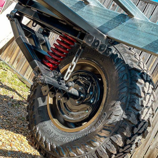
This allows each wheel to move completely independently. Each wheel gets its own swing arm, spring, and spindle. The simplest arrangement would be something like the trailer suspension kits shown above, modified to mount the hub motors.
I built a Lego prototype to test this out:
I wasn’t happy with it for a few reasons:
- Suspension travel is dictated by swing arm length — longer arm means more travel, but also larger moments on the bearings, which makes the wheels wobblier. You can see this in the prototype.
- The compliance allows excess body roll when traversing a slope with a high center of gravity.
- It’s complicated to build and maintain.
Solid Axle Suspension
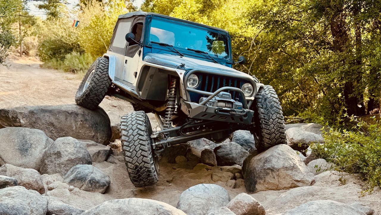
This connects the front and rear wheels with solid axles suspended to the chassis via a 4-bar linkage, similar to a rock crawler.
After watching a lot of RC rock crawler videos, I’m convinced this is more structurally sound than independent suspension — the axle just adds a lot of rigidity. The problem is that getting large suspension travel requires a long swing arm running fore/aft along the vehicle. In our case, the middle of the vehicle is already occupied by the steering pivot, so there’s not much room. We could extend the wheelbase, but that hurts maneuverability and moves the payload further inboard, increasing the bending moment on the pivot.
It also carries the same body roll risk on slopes, and seems expensive and difficult to build.
Articulated Pendulum Joint
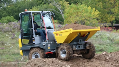
This is the approach used on many articulated machines in mining and construction — the Wacker Neuson DW30 above is a good example. These systems ditch springs and dampers entirely. Instead the pivot connecting the front and rear halves is free to rotate in both the yaw and roll axes. This keeps all four wheels in constant ground contact at all times. It’s essentially the same idea as the mars rover bogie suspension we looked at in an earlier post.
The benefits:
- Strong, rigid connection between wheels and chassis — simple, direct load path from payload to ground
- Plenty of wheel travel, since the full track width acts as the swing arm
- Good resistance to body roll on slopes — each half of the vehicle only rolls as far as the line between its two tire contact patches, it is not exacerbated by any suspension squish
- Easy to build, and flexible on motor placement since the motors can be mounted in the chassis itself
I’ve built a Lego prototype of this as well and I’m happy with how it performs — feels sturdy and rolls over bumps easily:
If it’s so good, why isn’t this used on road cars or rock crawlers? Honestly, I’m not 100% sure. My best guess is that without springs, only the tires are absorbing bump energy, which probably isn’t enough at highway speeds. It might work fine for a rock crawler, but those need to drive on-road to reach the trail. For RoBug, which tops out around 15 km/h, this isn’t a concern. Most of these articulated machines are rated above 15 km/hr.
The Pivot
The main challenge with this design is the pivot joint itself. It needs to:
- Rotate freely in yaw and roll
- Be completely rigid in pitch (this is the only thing controlling the pitch relationship between the two halves)
- Handle large fore/aft traction forces — for example, front wheels pulling the rear half up over a rock under full load
The industry standard is a 3-point articulated pendulum joint: a spherical plain bearing with a link connecting two points above it. The link locks out pitch while allowing roll. You can see one in action here.
For the prototype, I’ll likely build something similar using a trailer hitch ball and a tie rod with heim joints at each end.
But that’s a topic for another post.