Drivetrain Concept
Starting with the numbers
Before choosing a drivetrain, I needed to know how much power to drive it with.
RoBug’s specs call for a 250 kg payload capacity. I estimate the unloaded machine will weigh around 200 kg — so all-up loaded mass is 450 kg. The terrain requirement is a 20% slope (roughly 11°). The max speed of the vehicle is 10 km/hr, but that is for the unloaded vehicle. The maxmimum fully loaded speed will be more like 5 km/hr, or 1.4 m/s.
Running the numbers on traction power for a wheeled vehicle:
P = V x [m × g × sin(θ) + m × g × Crr × cos(θ)]
Where rolling resistance coefficient (Crr) for rough terrain is around 0.15 we get 2,600 W. Let’s round it up to have some buffer. 3,000 W of traction power. That’s the target.
Now — how do you deliver that to the ground, across Canadian Shield terrain, with a machine you can actually build in a garage?
Tracks
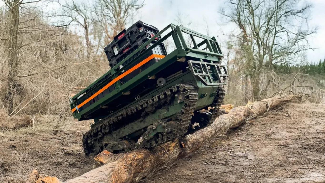
They distribute ground pressure over a large area, provide excellent traction, and handle soft ground far better than wheels. The Ferocarrier I looked at in the first post uses tracks precisely because of this.
But the problems are real. Building a functional track system from scratch — idlers, drive sprockets, track tensioners, the track itself — is a significant fabrication challenge. And once built, tracks are maintenance-intensive. Mud and debris pack into the drive mechanism. Tracks will often come off the idlers if not designed properly.
Unfortuantely, tracks are out.
Fixed-wheel 4WD skid steer
The simplest wheeled option: four wheels, each with its own motor, no suspension. Turn by running one side faster than the other — classic skid steer, the same principle used by tanks and countless small robot platforms.
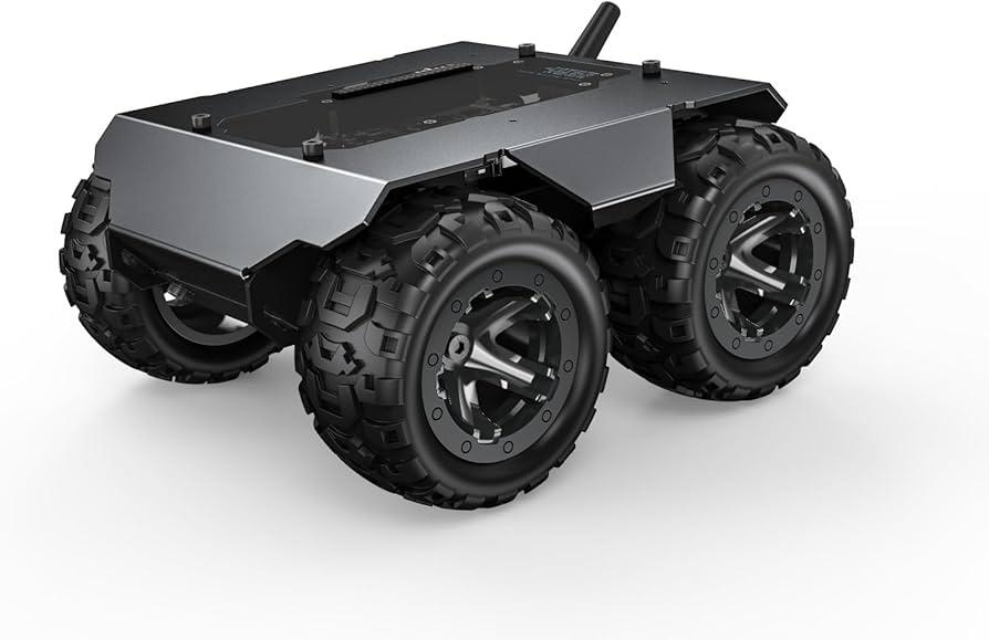
Lots of robot rovers use this successfully. It’s cheap, easy to build, and easy to control. The problem is that without suspension on uneven terrain only three of the four wheels are in firm contact with the ground at any time.
Three-point contact isn’t the end of the world but I think we can do better.
ATV-style independent suspension
If you want proven off-road performance, look at what ATVs and UTVs do.
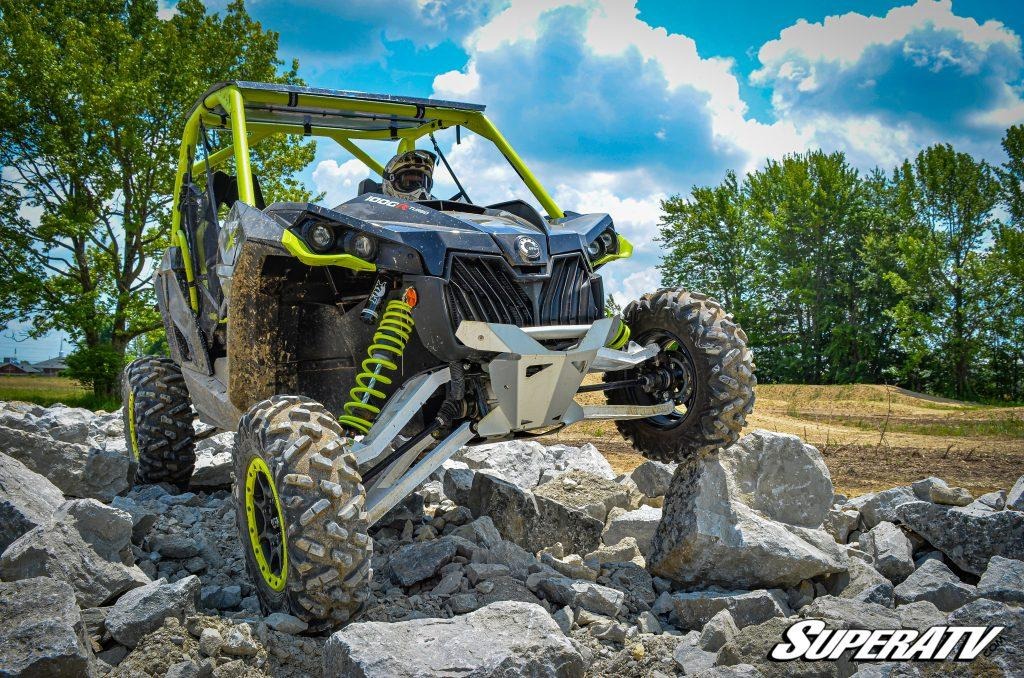
Independent suspension at each corner — coilovers, control arms, uprights — gives you great wheel travel and keeps tyres planted on uneven ground. It’s a tested, mature design.
The problem is the mechanical complexity. Control arms, uprights, bearings, spring perches, shock absorbers — each of these components needs to be sourced or designed and fabricated by me. It’s doable for a professional fabricator. For a garage build, it’s a substantial scope creep risk. So independent suspesion is out for the same reason as tracks, too complicated.
Rock crawler 4-bar suspension
Rock crawlers use a simpler suspension than ATVs — a 4-bar linkage at each corner rather than independent control arms. These vehicles are genuinely impressive off-road.
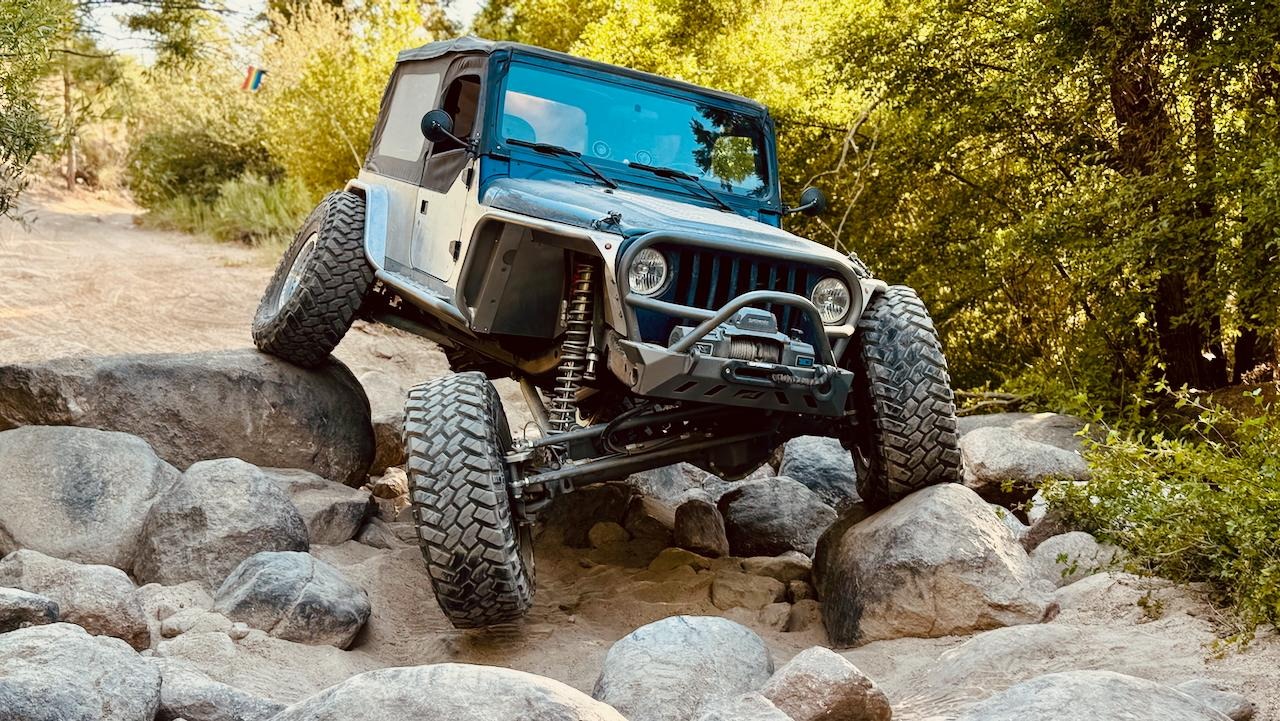
The 4-bar is a little simpler to fabricate than independent suspension. Rock crawlers need axles to transmit power to the wheels. If I’m going with hub motors — at this point I think they make sense — I don’t need axles at all. Surely that frees me up to build something even more capable.
Off-road suspension with hub motors
What vehicles use hub motors and are designed for extreme off-road capability?
The Mars Rovers.
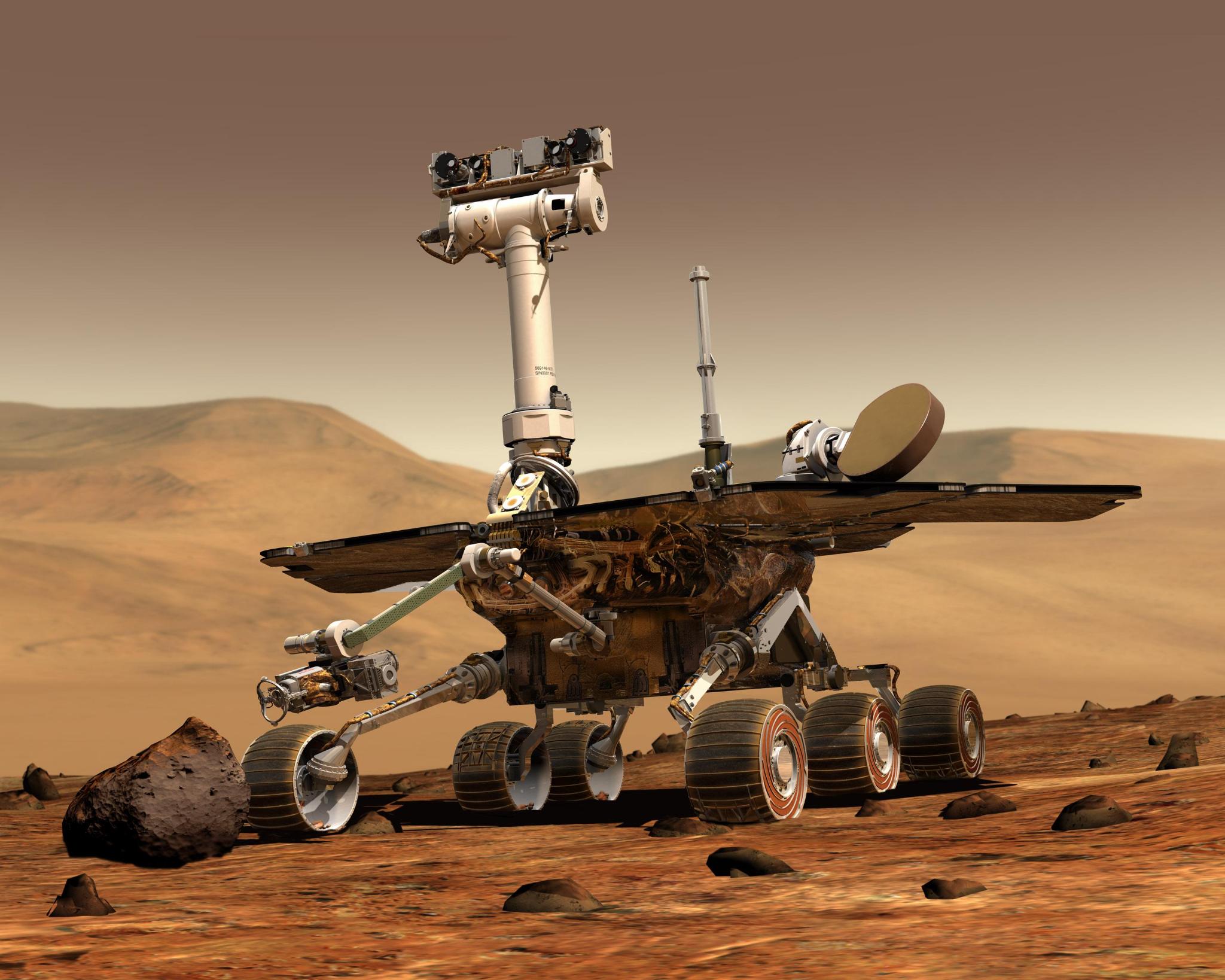
Curiosity and Perseverance use a rocker-bogie suspension system that keeps all six wheels in constant contact with the ground regardless of terrain. The geometry is elegant: two rockers on either side, connected at a pivot point on the chassis, with a bogie at the rear of each rocker carrying two wheels. The front of each rocker has a single wheel.
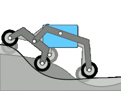
The catch is that pivot point. Because the two rockers pivot independently, there’s nothing to constrain the pitch of the chassis relative to the rockers — the chassis would just flop forward or backward. NASA solves this with a differential in the pivot connecting the two rocker shafts. The chassis is constrained by the differential housing. Again, this not something I want to source or fabricate.
3-bogie suspension
Fortunately, people way smarter than me have come up with a different approach.
The 3-bogie system uses three independent bogies — one on each side of the vehicle, and one at the rear — each carrying two wheels (six total). The chassis mounts to all three bogies through pivoting connections.
The rear bogie is rotated 90° relative to the side bogies. Together, all three bogies constrain the chassis in roll and pitch — no differential required.
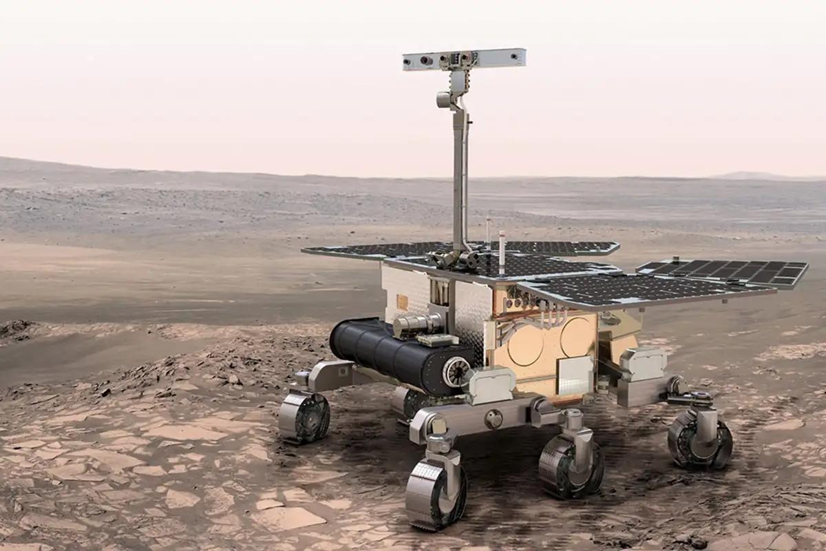
This is the approach the European Space Agency took for the ExoMars rover.
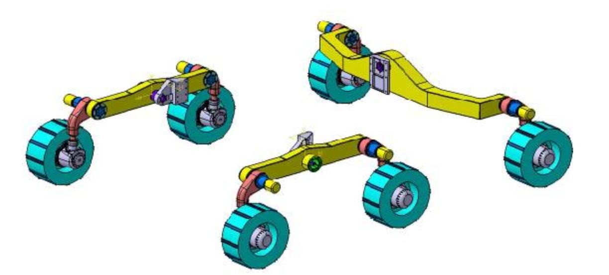
Three bogies, six wheels, six hub motors, full terrain contact. Very capable, dead simple. This is the design.
Why no springs?
One thing puzzled me at first: rock crawlers and ATVs need springs and dampers, but Mars rovers don’t. What’s going on?
I think it comes down to two things: speed and passengers.
Springs and dampers exist to manage energy. When a wheel hits a rock at speed, the spring stores and releases that energy gradually instead of transmitting it as a shock through the chassis. The damper bleeds off the energy so the chassis doesn’t bounce. At low speeds, the energy involved is small enough that passive geometry can handle it without dedicated spring elements. At least that’s my hope.
The other reason is that Mars rovers don’t carry humans. Suspension on a vehicle with a driver needs to protect the driver from vibration and shock. RoBug is not going to carry passengers, so vibrations are less of an issue.
Power: 6 × 500 W
With six driven wheels, I need each motor to deliver 500 W to meet the 3,000 W traction target.
Six hub motors is a clean fit. No gearboxes, no chains, no sprockets. Each bogie is a self-contained unit with two motor-wheels. I could easily remove each to fit the rover in the back of our car.
Steering: tank steer, not corner servos
There’s one significant way RoBug diverges from the NASA/ESA rover design: steering.
Every six-wheeled Mars rover steers by pivoting the corner wheels around their vertical axis — active steering servos in the corner hubs. This gives precise, low-scrub turning. It also means four steering actuators, pivot bearings at each corner, and a steering control system on top of the drive control system.
I’m not building that.
Instead, RoBug will tank steer — run the left wheels faster than the right to turn, exactly like a skid steer robot. It’s less precise but requires zero additional hardware beyond the drive motors I already need.
To reduce scrub, I’ll design RoBug with a shorter wheelbase relative to its track width than the rover references. A more square footprint reduces the turning radius and the scrub distance on the outer wheels. The prototype will let me measure how much scrub actually happens on different surfaces before I commit to the full RoBug dimensions.
Where we are
The mechanical concept:
- 6WD, 6 hub motors — 500 W each, 3,000 W total traction power
- 3-bogie suspension - all six wheels in constant ground contact, no differential, no springs
- Tank steering — differential drive, no corner servos
- Compact L/W ratio — to keep tank-steer scrub manageable
Next up: translating this into a fabricable frame design and sourcing the structural materials.